1) Rotary Limit Switch Adjustment
Tools required: Phillips Head screwdriver, Small Slotted Head Screwdriver,
For this procedure “Remote” is used to identify the TEC Boat Lift Remote Control Box.
Transmitter is the handheld control key-fob.
Turn OFF Auto Control switch if so equipped.
Use the Manual Up-Down switch on the side of the Remote enclosure.
This procedure may best be performed with an assistant.
-
Remove limit switch cover by loosening the two screws.
-
Press Up manual Toggle switch on the enclosure and
observe the direction that the two cams turn.
When your lift is at the maximum desired height release the button.
If the lift did not go as high as you need before stopping follow steps 3 and 4 to achieve this height.
Call the TEC Remote Factory for additional assistance.
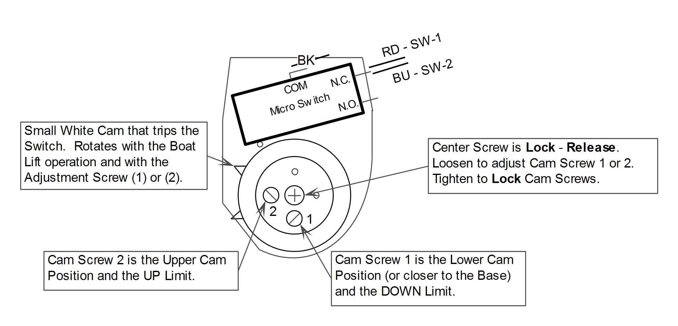
Adjustment Procedures:
-
Your lift should be at the maximum desired height.
Loosen center lock screw shown in the picture below ¾ turn.
-
Adjust the upper limit using screw 2 (blue wire).
Adjust the screw so the cam hits the micro switch roller arm
in the direction that the cam was turning so the leading edge of the cam trips the switch.
You will hear a small click (microswitch). If the roller arm is already on the cam,
back it away and move the lift then readjust.
-
Press the Up toggle switch on the enclosure.
The lift should not turn on. Re-tighten center lock screw!!
-
Now press the Down toggle switch on the enclosure.
Watch the cams to see that they travel away from the roller switch arm.
If the down switch trips and the unit will not lower, loosen center lock screw
and adjust the lower cam away from the roller switch arm, tighten the Lock screw, and continue.
-
When the lift is at the lowest point to be able to launch your boat at a low tide,
or before the lift hits bottom, or it has a minimum of 3 wraps of cable on the drive pipe,
adjust the bottom cam screw 1 until you hear a click.
Try pressing the down switch. The lift should not turn on.
-
Re-tighten the Center Lock screw before you activate the lift.
-
Turn on the Auto Control switch, if so equipped.
Operate the lift now with the Transmitter.
The lift should now run continuously by pressing a direction once on the Transmitter.
Run the lift up a foot then press the stop button, and the lift should stop.
Press down button (There is a 3 second delay when changing direction) and
make sure the lift stops at the lower limit, if not readjust the limit and test again.
Check the up limit to ensure proper operation.
Check that the lift stops in both directions.
-
FAILURE to follow these directions voids all warranties to equipment as written or implied.
TEC will not assume any responsibility for damages that are a result of improper installation or user error.
-
WARNING: Failure to tighten the Center Lock screw might not allow
the cams to move correctly, therefore the LIFT MAY NOT STOP.
This could possibly cause damage to the limit switch, boat lift, boat, and/or the entire system.
-
For maximum safety, we recommend that the TEC unit be turned off at the power source when not in use.
===================================================
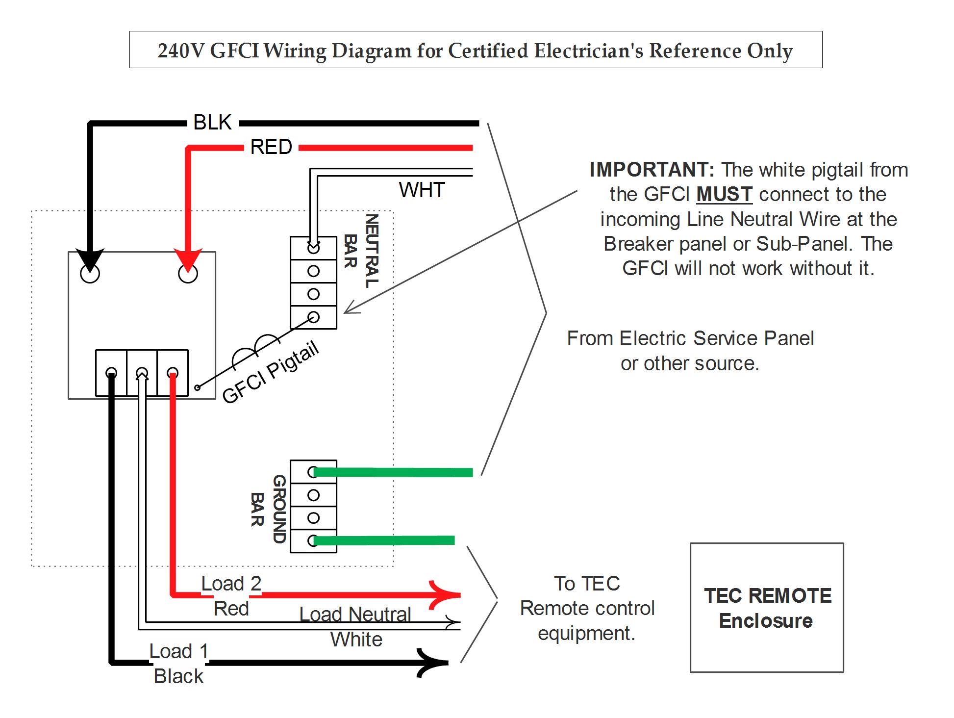
2) GFCI Wiring
===========================================
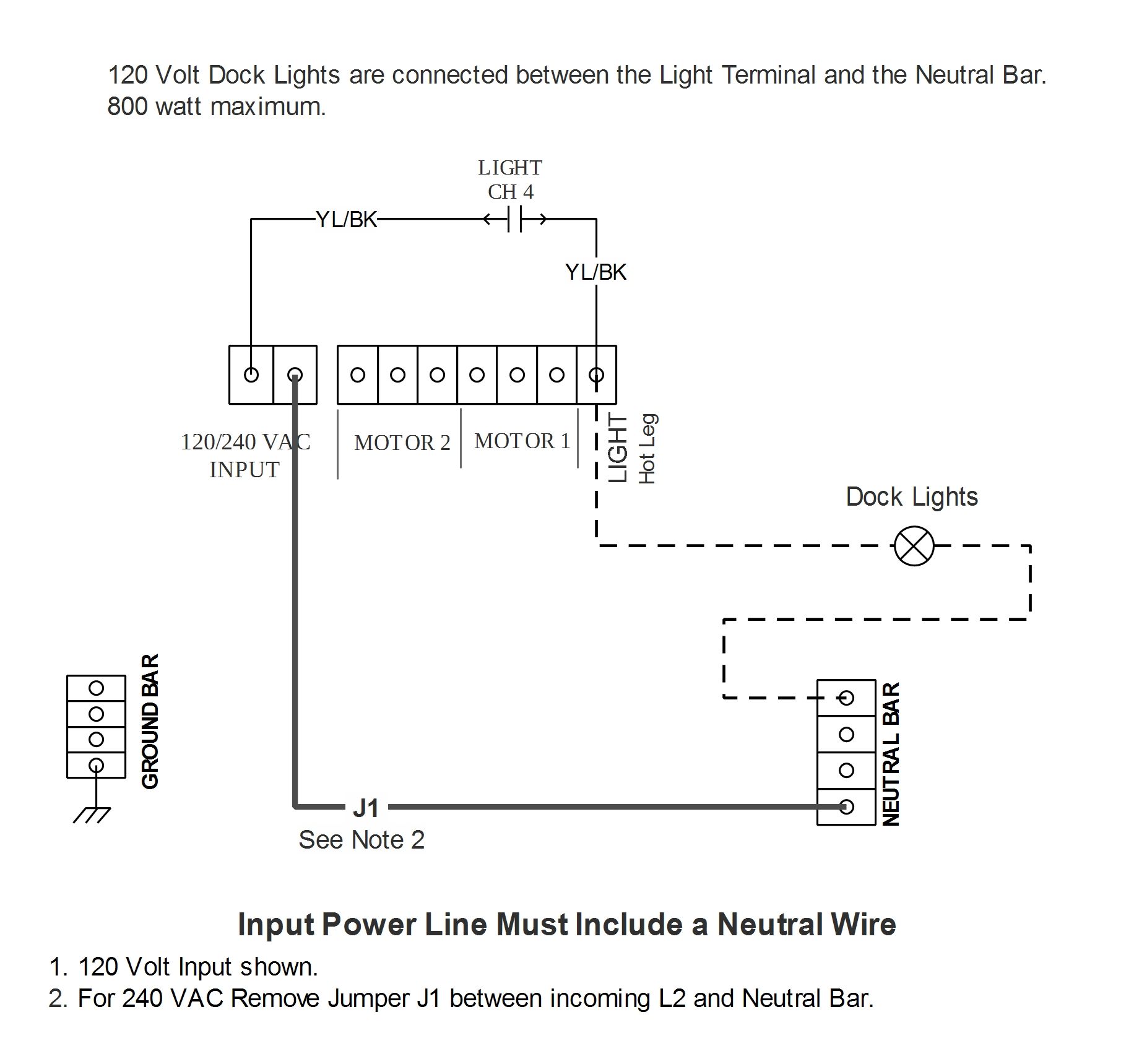
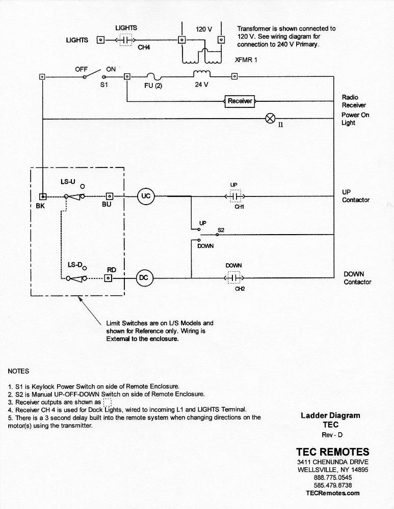
5) Light Wiring Diagram
===================================================
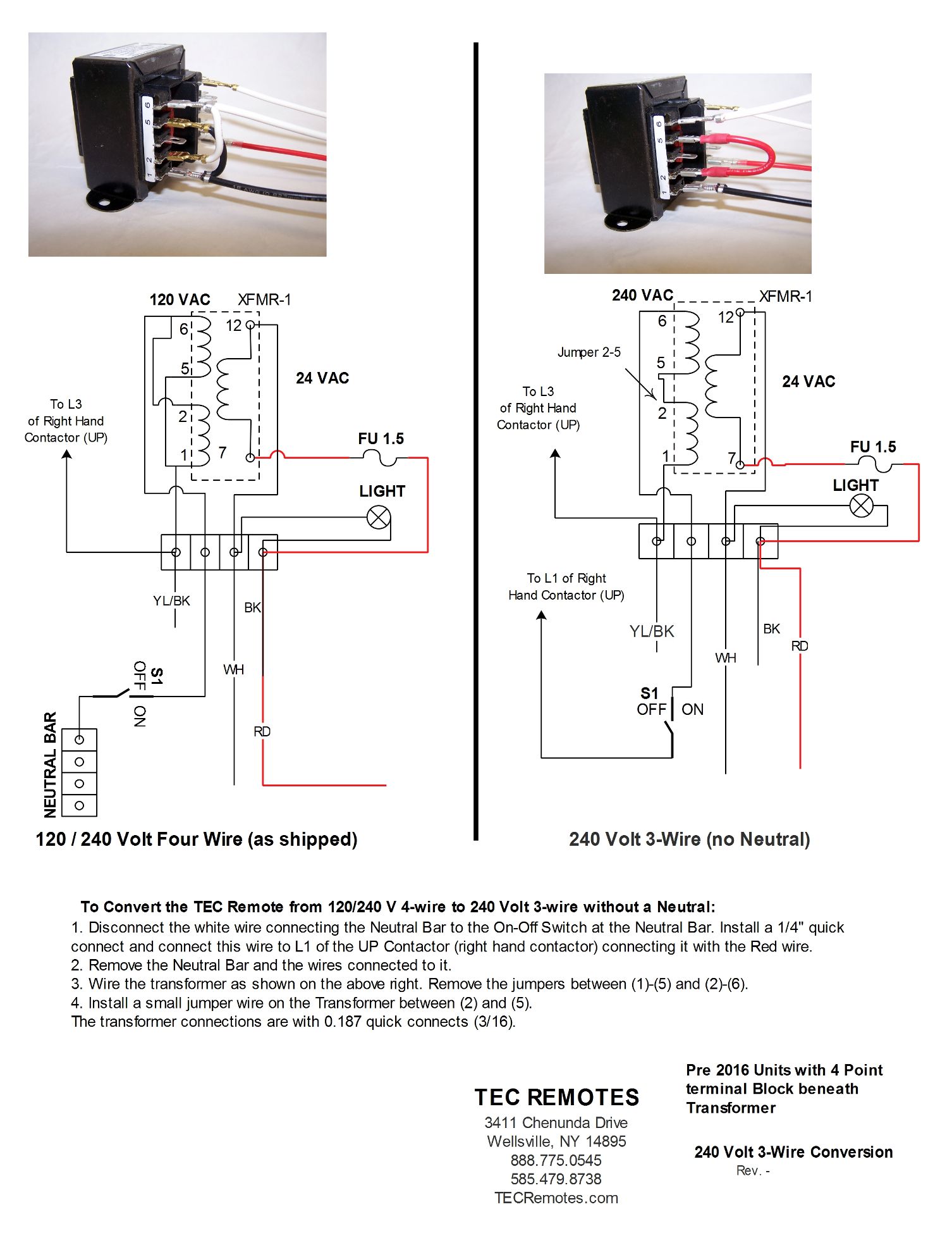
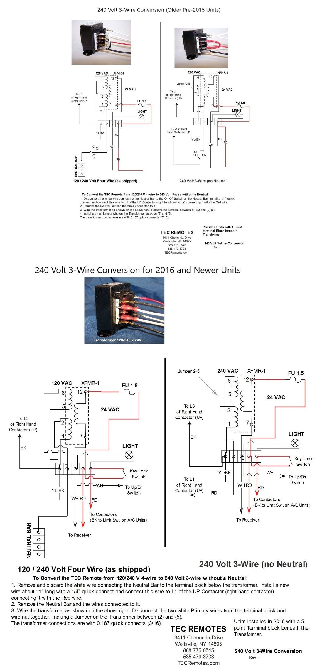
6) 240 Volt 3-Wire Conversion (Older Pre-2015 Units)
====================================================================

====================================================================


.jpg)
.jpg)
.jpg)
.jpg)
.jpg)